Tuesday, May 12, 2009 at 1:36 AM | 0 comments  

Subnetting

  • Dividing a Single Network into Multiple Networks.
  • Converting Host bits to Network Bits 
     i.e. Converting 0’s into 1’s
  • Subnetting is also called as FLSM (Fixed Length Subnet Mask)
  • Subnetting can be done in three ways.
  1. Requirement of Network
  2. Requirement of Host
  3. Cisco / Notation

Scenario

ZOOM Technologies is having 100 PC

  • Which Class IP addresses you will using in the network ?
     Answer : Class C.
  • In ZOOM Technologies we have Five Departments with 20 Pcs each

ZOOM Technologies – 192.168.1.0/24


  • Administrator Requirement 
     Inter-department communication should not be possible ? 
     
     Solution.
     Allocate a different Network to each Department
     i.e.


  • In the above Scenario inter-department communication is not possible.

Main Aim of Subnetting

Problem with the previous Scenario is :-

  • Instead of 20 machine Broadcasting, you doing broadcasting for 254 machine, Loss of bandwidth.
  • More Wasting of IP addresses (Approximately 1000)
  • Security


Power table


Some Important Values


Requirement of Networks is 5 ?
Example – 1

 
Class C : 192.168.1.0

If you convert 3 Host Bits to Network Bits
6 Subnet & 30 Hosts/Subnet

                              Customize Subnet Mask
                                   
255.255.255.224

                                                Subnet Range
                               
 192.168.1.32    to   192.168.1.63    ->MCSE .
                                 192.168.1.64    to   192.168.1.95    -> CISCO .
                                 192.168.1.96    to   192.168.1.127  ->FIREWALL
                                 192.168.1.128  to   192.168.1.159  ->SOLARIS
                                 192.168.1.160  to  192.168.1.191  ->TRAINING
                                 192.168.1.192  to  192.168.1.223  -> Future Use

Requirement of Networks is 14 ?
Example – 2 

lass C : 192.168.1.0


Try to do the calculation ?


Example – 2


Example – 3


Example – 4


Example – 5

bit to network bit.

Example – 6

Requirement of Hosts is 40 ?
Example – 1 


Requirement of Hosts is 2 ?
Example – 2 


Cisco / Notation
Example – 1 


Requirement of Networks is 2 ?
Example – 1 


Requirement of Hosts is 126 ?
Example – 2


Cisco / Notation
Example – 3 


Posted by CCNA MASTER
Thursday, May 7, 2009 at 12:27 AM | 0 comments  
  • IP Addressing is Logical Addressing

  • It works on Network Layer (Layer 3)

  • Two Version of Addressing Scheme
  1. IP version 4 – 32 bit addressing
  2. IP version 6 – 128 bit addressing

What is BIT ?

  • Bit is a value that will represent 0’s or 1’s (i.e. Binary)

        01010101000001011011111100000001

  • 32 bits are divided into 4 Octets known as Dotted Decimal Notation


  • 128-bit address is divided along 16-bit boundaries, and each 16-bit block is converted to a 4-digit hexadecimal number and separated by colons (Colon-Hex Notation) 

                         FEDC:BA98:7654:3210:FEDC:BA98:7654:3210

                             This discussion is out of the scope of CCNA

Binary to Decimal Conversion


IP Address Classes


Priority Bits Concept

  • To identify the range of each class 
     we will be using Priority Bit Concept
  • Priority Bit is the left most bits in the First Octet
  • CLASS A priority bit is                         0
  • CLASS B priority bit is                         10
  • CLASS C priority bit is                         110
  • CLASS D priority bit is                         1110
  • CLASS E priority bit is                         1111

CLASS A Range

For Class A range reserved first bit in 
first octet,the value of that bit should not change.


CLASS B Range

For Class B range reserved first two bit in 
first octet,the value of that bit should not change.


CLASS C Range

For Class C range reserved first three bit in 
first octet,the value of that bit should not change.

CLASS D Range

For Class D range reserved first four bit in 
first octet,the value of that bit should not change.


CLASS E Range
For Class E range reserved first four bit in 
first octet,the value of that bit should not change.


Octet Format

  • IP address is divided into Network & Host Portion
  • CLASS A is written as                              N.H.H.H
  • CLASS B is written as                              N.N.H.H
  • CLASS C is written as                              N.N.N.H


CLASS A – No. Networks & Host 

Class A Octet Format is N.H.H.H
Network bits : 8                     Host bits : 24

  • No. of Networks 
     = 28-1 (-1 is Priority Bit for Class A)
     = 27
     = 128 – 2 (-2 is for 0 & 127 Network)
     = 126 Networks
  • No. of Host  
     = 224 – 2 (-2 is for Network ID & Broadcast ID)
     = 16777216 - 2
     = 16777214 Hosts/Network


CLASS B – No. Networks & Host 

Class B Octet Format is N.N.H.H
Network bits : 16              Host bits : 16

  • No. of Networks 
     = 216-2 (-2 is Priority Bit for Class B)
     = 214
     = 16384 Networks
  • No. of Host  
     = 216 – 2 (-2 is for Network ID & Broadcast ID)
     = 65536 - 2
     = 65534 Hosts/Network


CLASS C – No. Networks & Host 

Class C Octet Format is N.N.N.H
Network bits : 24                 Host bits : 8

  • No. of Networks 
     = 224-3 (-3 is Priority Bit for Class C)
     = 221
     = 2097152 Networks
  • No. of Host  
     = 28 – 2 (-2 is for Network ID & Broadcast ID)
     = 256 - 2
     = 254 Hosts/Network


Network & Broadcast Address  

The network address is represented with all bits as ZERO in the host portion of the address

The broadcast address
is represented with all bits as ONES in the host portion of the address

Valid IP Addresses lie between the Network Address and the Broadcast Address. 

Only Valid IP Addresses are assigned to hosts/clients

Example - Class A 


Example - Class B 


Example - Class C


Private IP Address

  • There are certain addresses in each class of IP address that are reserved for LAN. These addresses are called private addresses.
  • They can be used for: home & office networks, ATM machines, networks not connected to Internet.


Subnet Mask

  • Subnet Mask differentiates Network portion and Host Portion
  • Subnet Mask is been given for host Identification of Network ID
  • Represent all Network Bit Values with 1
  • Represent all Host Bit Values with 0

Subnet Mask - Examples 


How Subnet Mask Works ?

IP Address     : 192.168.1.1
Subnet Mask :  255.255.255.0

192.168.1.1       = 11000000.10101000.00000001.00000001
255.255.255.0 = 11111111.11111111.11111111.00000000
============================================
192.168.1.0      = 11000000.10101000.00000001.00000000
============================================

Above Calculations is done with the Help of AND Table. 
The output of an AND table is only 1 if both its inputs are 1. 
For all other possible inputs the output is 0.


Posted by CCNA MASTER
Wednesday, May 6, 2009 at 10:16 PM | 0 comments  
  • OSI means Open System Interconnect model.
  • Developed by the International Organization for Standardization in 1984.
  • It consists of seven layers.
  • Each layer has a different but specific processing function.


OSI Model Layers


Application Layer


  •  Application Layer is responsible for providing Networking Services to user. It also known  as Desktop Layer. Identification of Services is done using Port Numbers.

     Ports are nothing but Socket i.e. Entry and Exit Point to the Layer

      Total No. Ports 0 – 65535 
      Reserved Ports 0 – 1023
      Open Ports 1024 – 65535

Examples of Networking Services

Service                                              Port No.
HTTP                                                  80 
FTP                                                      21
SMTP                                                  25
TELNET                                             23
TFTP                                                   69

How data flows from Application Layer


Presentation Layer


 Presentation Layer is responsible for converting data into standard format. 

 Examples : ASCII, EBCDIC, JPEG, MPEG, BMP, MIDI, WAV, MP3

 Following tasks are perform at Presentation layer :

 Encoding – Decoding
 Encryption – Decryption
 Compression – Decompression 


How data flows from Presentation Layer


Session Layer


 Session Layer is responsible establishing, maintaining and terminating session. 
 Session ID also works at Session Layer.

 Examples :

 RPC  Remote Procedure Call 
 SQL  Structured Query language
 NFS  Network File System


How data flows from Session Layer


Transport Layer


Transport Layer
is responsible for end-to-end connectivity. It is also known as heart of OSI Layers. Following task are performed at Transport Layer : - 

  • Identifying Service
  • Multiplexing & De-multiplexing
  • Segmentation
  • Sequencing & Reassembling
  • Flow Control
  • Error Correction


Identifying Service


Multiplexing & De-multiplexing


Segmentation


Sequencing & Reassembling


Sequencing & Reassembling


Error Correction


Flow Control - Windowing


How data flows from Transport Layer


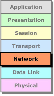
Network Layer


Network Layer is responsible for providing best path to data to reach destination. Logical Addressing sits on this layer. Device working on Network Layer is Router.

It is divided into two parts 
Routed Protocols
e.g. IP, IPX, Apple Talk.
Routing Protocols
e.g. RIP, IGRP, OSPF, EIGRP

Routed Protocols


Routing Protocols


How data flows from Network Layer


Datalink Layer


Datalink Layer is divided into two Sub Layers :

LLC – Logical Link Control
It talks about Wan protocols e.g. PPP, HDLC, Frame-relay

MAC – Media Access Control
It talks about Physical Address. It is 48 bit Addressing i.e. 12 digit Hexadecimal No. It is also responsible for Error Detection
Device working on Data Link Layer is Switch, Bridge, NIC.

Error Detection – CRC Check


Error Detection – CRC Check


How data flows from Data Link Layer


Physical Layer


Physical Layer is responsible for electrical, mechanical or procedural checks. Data will be converted in Binary that is 0’s & 1’s. Data will be in the form of electrical pulses if it is Coaxial or Twisted Pair cable and in the form of Light if it is Fiber Optic Cable.

Devices working at Physical
Layer are Hubs, Repeaters, Cables, Modems etc.

Physical Layer Example


How data flows from Physical Layer


Data Encapsulation & De-capsulation


Comparing OSI with TCP/IP Layers 


Posted by CCNA MASTER